Tag Archives: dc motor

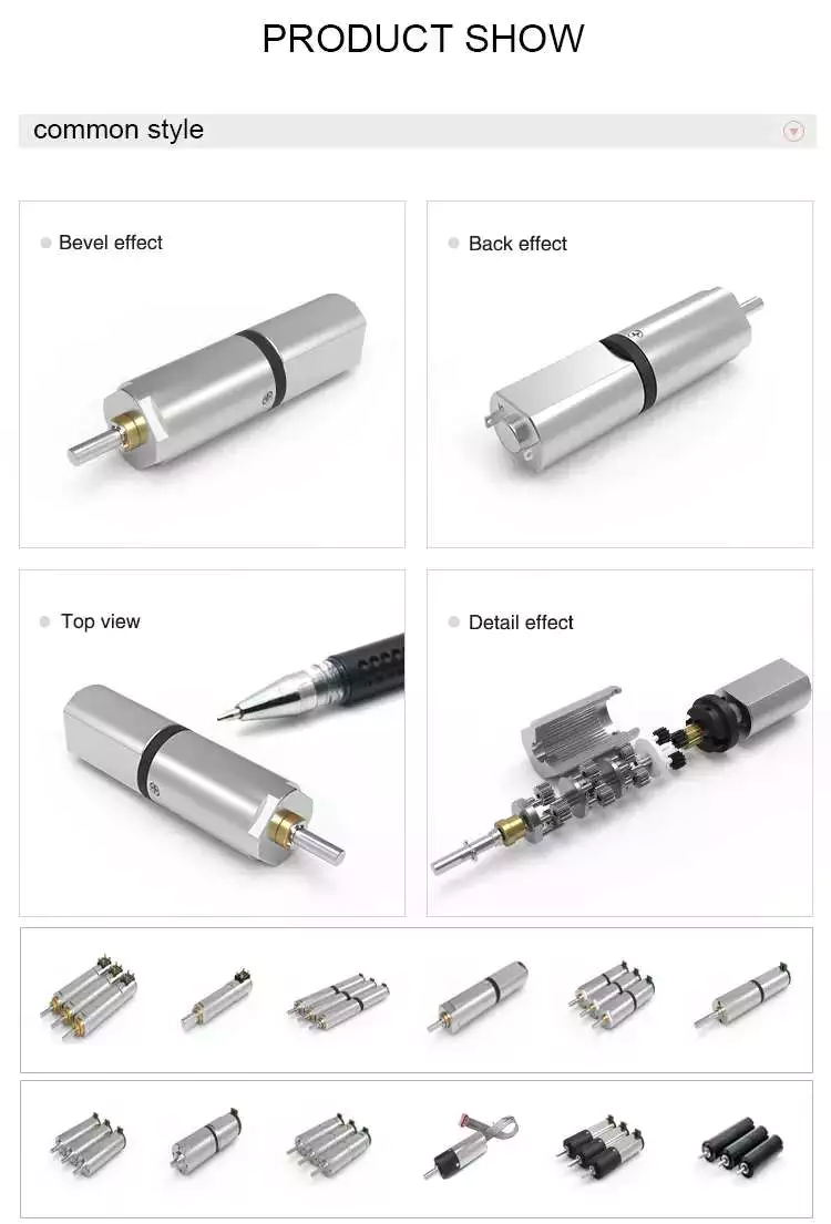
China 24mm 12v Dc Dear Motor Micro Planetary Gearbox Permanent straight bevel gear

Guarantee: 3 years
Applicable Industries: Other, H2o pump and air pump, Electric curtain, Devices and tools
Weight (KG): .5 KG
Custom-made assistance: OEM, ODM, OBM
Gearing Arrangement: Planetary
Enter Velocity: 1 Substantial Top quality equivalents to Rexnord Falk steelflex grid coupling Therapeutic massage Gun,Fan,air cleaner,Hair elimination System,doorway lock,Clever doorway lock.Drinking water pump.Air Multiplier.Meals and BeverageHand Blenders, Blenders, Mixers, Coffee Equipment, Meals Processors, Juicers, Fryers, Ice Makers, Soy Bean Milk Makers.Medicalsphygmomanometer, Massaging mattress, Air pump, Urine Analyzer.RoboticsSweeping Robot.Servicing robotics, Foods shipping robot, Reception robotic, Health-related serving robot, Convenying robotic, Inspection robot.Underwater robot. Firm Profile HangZhou CZPT motor HangZhou CZPT Motor Co., Ltd. is a specialist brushless motor analysis and development and production producers. In 2019, it passed the nationwide large-tech business certification. The organization has a team of 20 several years engaged in the motor business senior R & CV Axles Travel Shaft Scorching SALE OUTER CV JOINT C.V. JOINT GM-757 for CZPT automobile automobile D engineering crew, has abundant expertise in procedure engineering and manufacturing management, and the introduction of the most superior automated production products and Japan and Germany imported testing tools. Top quality initial, ongoing enhancement, CZPT is our objective. Our motors are widely employed in medical gadgets, intelligent residences, house appliances, h2o pumps,air pumps, intelligent toys, recreation consoles, energy resources, health tools, individual treatment goods and other fields. VR Gear & Generation line Certifications Packing & Supply Shipping time:DHL: 3-5 operating times UPS: 5-7 doing work times TNT: 5-7 doing work times FedEx: 7-9 operating times EMS: 12-15 working daysPost: Relies upon on ship to which region Sea: Relies upon on ship to which place.To much better guarantee the security of your goods, specialist, environmentally pleasant, wholesale clutch assy spare pars of chainsaw clutch practical and productive packaging solutions will be presented.

packagingMeasurement of circumstanceGross weight of carton
cartons375mm*260mm*265mm.48kg
Why Select Us Services hotline

Gear

Spiral Gears for Right-Angle Right-Hand Drives

Spiral gears are used in mechanical systems to transmit torque. The bevel gear is a particular type of spiral gear. It is made up of two gears that mesh with one another. Both gears are connected by a bearing. The two gears must be in mesh alignment so that the negative thrust will push them together. If axial play occurs in the bearing, the mesh will have no backlash. Moreover, the design of the spiral gear is based on geometrical tooth forms.

Equations for spiral gear

The theory of divergence requires that the pitch cone radii of the pinion and gear be skewed in different directions. This is done by increasing the slope of the convex surface of the gear’s tooth and decreasing the slope of the concave surface of the pinion’s tooth. The pinion is a ring-shaped wheel with a central bore and a plurality of transverse axes that are offset from the axis of the spiral teeth.
Spiral bevel gears have a helical tooth flank. The spiral is consistent with the cutter curve. The spiral angle b is equal to the pitch cone’s genatrix element. The mean spiral angle bm is the angle between the genatrix element and the tooth flank. The equations in Table 2 are specific for the Spread Blade and Single Side gears from Gleason.
The tooth flank equation of a logarithmic spiral bevel gear is derived using the formation mechanism of the tooth flanks. The tangential contact force and the normal pressure angle of the logarithmic spiral bevel gear were found to be about twenty degrees and 35 degrees respectively. These two types of motion equations were used to solve the problems that arise in determining the transmission stationary. While the theory of logarithmic spiral bevel gear meshing is still in its infancy, it does provide a good starting point for understanding how it works.
This geometry has many different solutions. However, the main two are defined by the root angle of the gear and pinion and the diameter of the spiral gear. The latter is a difficult one to constrain. A 3D sketch of a bevel gear tooth is used as a reference. The radii of the tooth space profile are defined by end point constraints placed on the bottom corners of the tooth space. Then, the radii of the gear tooth are determined by the angle.
The cone distance Am of a spiral gear is also known as the tooth geometry. The cone distance should correlate with the various sections of the cutter path. The cone distance range Am must be able to correlate with the pressure angle of the flanks. The base radii of a bevel gear need not be defined, but this geometry should be considered if the bevel gear does not have a hypoid offset. When developing the tooth geometry of a spiral bevel gear, the first step is to convert the terminology to pinion instead of gear.
The normal system is more convenient for manufacturing helical gears. In addition, the helical gears must be the same helix angle. The opposite hand helical gears must mesh with each other. Likewise, the profile-shifted screw gears need more complex meshing. This gear pair can be manufactured in a similar way to a spur gear. Further, the calculations for the meshing of helical gears are presented in Table 7-1.
Gear

Design of spiral bevel gears

A proposed design of spiral bevel gears utilizes a function-to-form mapping method to determine the tooth surface geometry. This solid model is then tested with a surface deviation method to determine whether it is accurate. Compared to other right-angle gear types, spiral bevel gears are more efficient and compact. CZPT Gear Company gears comply with AGMA standards. A higher quality spiral bevel gear set achieves 99% efficiency.
A geometric meshing pair based on geometric elements is proposed and analyzed for spiral bevel gears. This approach can provide high contact strength and is insensitive to shaft angle misalignment. Geometric elements of spiral bevel gears are modeled and discussed. Contact patterns are investigated, as well as the effect of misalignment on the load capacity. In addition, a prototype of the design is fabricated and rolling tests are conducted to verify its accuracy.
The three basic elements of a spiral bevel gear are the pinion-gear pair, the input and output shafts, and the auxiliary flank. The input and output shafts are in torsion, the pinion-gear pair is in torsional rigidity, and the system elasticity is small. These factors make spiral bevel gears ideal for meshing impact. To improve meshing impact, a mathematical model is developed using the tool parameters and initial machine settings.
In recent years, several advances in manufacturing technology have been made to produce high-performance spiral bevel gears. Researchers such as Ding et al. optimized the machine settings and cutter blade profiles to eliminate tooth edge contact, and the result was an accurate and large spiral bevel gear. In fact, this process is still used today for the manufacturing of spiral bevel gears. If you are interested in this technology, you should read on!
The design of spiral bevel gears is complex and intricate, requiring the skills of expert machinists. Spiral bevel gears are the state of the art for transferring power from one system to another. Although spiral bevel gears were once difficult to manufacture, they are now common and widely used in many applications. In fact, spiral bevel gears are the gold standard for right-angle power transfer.While conventional bevel gear machinery can be used to manufacture spiral bevel gears, it is very complex to produce double bevel gears. The double spiral bevel gearset is not machinable with traditional bevel gear machinery. Consequently, novel manufacturing methods have been developed. An additive manufacturing method was used to create a prototype for a double spiral bevel gearset, and the manufacture of a multi-axis CNC machine center will follow.
Spiral bevel gears are critical components of helicopters and aerospace power plants. Their durability, endurance, and meshing performance are crucial for safety. Many researchers have turned to spiral bevel gears to address these issues. One challenge is to reduce noise, improve the transmission efficiency, and increase their endurance. For this reason, spiral bevel gears can be smaller in diameter than straight bevel gears. If you are interested in spiral bevel gears, check out this article.
Gear

Limitations to geometrically obtained tooth forms

The geometrically obtained tooth forms of a spiral gear can be calculated from a nonlinear programming problem. The tooth approach Z is the linear displacement error along the contact normal. It can be calculated using the formula given in Eq. (23) with a few additional parameters. However, the result is not accurate for small loads because the signal-to-noise ratio of the strain signal is small.
Geometrically obtained tooth forms can lead to line and point contact tooth forms. However, they have their limits when the tooth bodies invade the geometrically obtained tooth form. This is called interference of tooth profiles. While this limit can be overcome by several other methods, the geometrically obtained tooth forms are limited by the mesh and strength of the teeth. They can only be used when the meshing of the gear is adequate and the relative motion is sufficient.
During the tooth profile measurement, the relative position between the gear and the LTS will constantly change. The sensor mounting surface should be parallel to the rotational axis. The actual orientation of the sensor may differ from this ideal. This may be due to geometrical tolerances of the gear shaft support and the platform. However, this effect is minimal and is not a serious problem. So, it is possible to obtain the geometrically obtained tooth forms of spiral gear without undergoing expensive experimental procedures.
The measurement process of geometrically obtained tooth forms of a spiral gear is based on an ideal involute profile generated from the optical measurements of one end of the gear. This profile is assumed to be almost perfect based on the general orientation of the LTS and the rotation axis. There are small deviations in the pitch and yaw angles. Lower and upper bounds are determined as – 10 and -10 degrees respectively.
The tooth forms of a spiral gear are derived from replacement spur toothing. However, the tooth shape of a spiral gear is still subject to various limitations. In addition to the tooth shape, the pitch diameter also affects the angular backlash. The values of these two parameters vary for each gear in a mesh. They are related by the transmission ratio. Once this is understood, it is possible to create a gear with a corresponding tooth shape.
As the length and transverse base pitch of a spiral gear are the same, the helix angle of each profile is equal. This is crucial for engagement. An imperfect base pitch results in an uneven load sharing between the gear teeth, which leads to higher than nominal loads in some teeth. This leads to amplitude modulated vibrations and noise. In addition, the boundary point of the root fillet and involute could be reduced or eliminate contact before the tip diameter.

China 24mm 12v Dc Dear Motor Micro Planetary Gearbox Permanent     straight bevel gearChina 24mm 12v Dc Dear Motor Micro Planetary Gearbox Permanent     straight bevel gear
editor by Cx 2023-06-21

China 25mm Brushed DC Gear Motor for Home Appliance worm gearbox

Product Description

We are a professional manufacuter for Dc motor, equipment motor, brush and brushless motor because 2006.


US $1
/ Piece
|
1,000 Pieces

(Min. Order)

###

Application: Household Appliances
Operating Speed: High Speed
Excitation Mode: Compound
Function: Driving
Casing Protection: Explosion-Proof Type
Number of Poles: 2

###

Samples:
US$ 0.1/Piece
1 Piece(Min.Order)

|
Request Sample

###

Customization:

Benefits and Uses of Miter Gears

If you’ve ever looked into the differences between miter gears, you’re probably wondering how to choose between a Straight toothed and Hypoid one. Before you decide, however, make sure you know about backlash and what it means. Backlash is the difference between the addendum and dedendum, and it prevents jamming of the gears, protects the mating gear surfaces, and allows for thermal expansion during operation.
gear

Spiral bevel gears

Spiral bevel gears are designed to increase efficiency and reduce cost. The spiral shape creates a profile in which the teeth are cut with a slight curve along their length, making them an excellent choice for heavy-duty applications. Spiral bevel gears are also hypoid gears, with no offsets. Their smaller size means that they are more compact than other types of right-angle gears, and they are much quieter than other types of gear.
Spiral bevel gears feature helical teeth arranged in a 90-degree angle. The design features a slight curve to the teeth, which reduces backlash while increasing flexibility. Because they have no offsets, they won’t slip during operation. Spiral bevel gears also have less backlash, making them an excellent choice for high-speed applications. They are also carefully spaced to distribute lubricant over a larger area. They are also very accurate and have a locknut design that prevents them from moving out of alignment.
In addition to the geometric design of bevel gears, CZPT can produce 3D models of spiral bevel gears. This software has gained widespread attention from many companies around the world. In fact, CZPT, a major manufacturer of 5-axis milling machines, recently machined a prototype using a spiral bevel gear model. These results prove that spiral bevel gears can be used in a variety of applications, ranging from precision machining to industrial automation.
Spiral bevel gears are also commonly known as hypoid gears. Hypoid gears differ from spiral bevel gears in that their pitch surface is not at the center of the meshing gear. The benefit of this gear design is that it can handle large loads while maintaining its unique features. They also produce less heat than their bevel counterparts, which can affect the efficiency of nearby components.

Straight toothed miter gears

Miter gears are bevel gears that have a pitch angle of 90 degrees. Their gear ratio is 1:1. Miter gears come in straight and spiral tooth varieties and are available in both commercial and high precision grades. They are a versatile tool for any mechanical application. Below are some benefits and uses of miter gears. A simple explanation of the basic principle of this gear type is given. Read on for more details.
When selecting a miter gear, it is important to choose the right material. Hard faced, high carbon steel is appropriate for applications requiring high load, while nylon and injection molding resins are suitable for lower loads. If a particular gear becomes damaged, it’s advisable to replace the entire set, as they are closely linked in shape. The same goes for spiral-cut miter gears. These geared products should be replaced together for proper operation.
Straight bevel gears are the easiest to manufacture. The earliest method was using an indexing head on a planer. Modern manufacturing methods, such as the Revacycle and Coniflex systems, made the process more efficient. CZPT utilizes these newer manufacturing methods and patented them. However, the traditional straight bevel is still the most common and widely used type. It is the simplest to manufacture and is the cheapest type.
SDP/Si is a popular supplier of high-precision gears. The company produces custom miter gears, as well as standard bevel gears. They also offer black oxide and ground bore and tooth surfaces. These gears can be used for many industrial and mechanical applications. They are available in moderate quantities from stock and in partial sizes upon request. There are also different sizes available for specialized applications.
gear

Hypoid bevel gears

The advantages of using Hypoid bevel and helical gears are obvious. Their high speed, low noise, and long life make them ideal for use in motor vehicles. This type of gear is also becoming increasingly popular in the power transmission and motion control industries. Compared to standard bevel and helical gears, they have a higher capacity for torque and can handle high loads with less noise.
Geometrical dimensioning of bevel/hypoid bevel gears is essential to meet ANSI/AGMA/ISO standards. This article examines a few ways to dimension hypoid bevel and helical gears. First, it discusses the limitations of the common datum surface when dimensioning bevel/helical gear pairs. A straight line can’t be parallel to the flanks of both the gear and the pinion, which is necessary to determine “normal backlash.”
Second, hypoid and helical gears have the same angular pitch, which makes the manufacturing process easier. Hypoid bevel gears are usually made of two gears with equal angular pitches. Then, they are assembled to match one another. This reduces noise and vibration, and increases power density. It is recommended to follow the standard and avoid using gears that have mismatched angular pitches.
Third, hypoid and helical gears differ in the shape of the teeth. They are different from standard gears because the teeth are more elongated. They are similar in appearance to spiral bevel gears and worm gears, but differ in geometry. While helical gears are symmetrical, hypoid bevel gears are non-conical. As a result, they can produce higher gear ratios and torque.

Crown bevel gears

The geometrical design of bevel gears is extremely complex. The relative contact position and flank form deviations affect both the paired gear geometry and the tooth bearing. In addition, paired gears are also subject to process-linked deviations that affect the tooth bearing and backlash. These characteristics require the use of narrow tolerance fields to avoid quality issues and production costs. The relative position of a miter gear depends on the operating parameters, such as the load and speed.
When selecting a crown bevel gear for a miter-gear system, it is important to choose one with the right tooth shape. The teeth of a crown-bevel gear can differ greatly in shape. The radial pitch and diametral pitch cone angles are the most common. The tooth cone angle, or “zerol” angle, is the other important parameter. Crown bevel gears have a wide range of tooth pitches, from flat to spiral.
Crown bevel gears for miter gear are made of high-quality materials. In addition to metal, they can be made of plastic or pre-hardened alloys. The latter are preferred as the material is less expensive and more flexible than steel. Furthermore, crown bevel gears for miter gears are extremely durable, and can withstand extreme conditions. They are often used to replace existing gears that are damaged or worn.
When selecting a crown bevel gear for a miter gear, it is important to know how they relate to each other. This is because the crown bevel gears have a 1:1 speed ratio with a pinion. The same is true for miter gears. When comparing crown bevel gears for miter gears, be sure to understand the radii of the pinion and the ring on the pinion.
gear

Shaft angle requirements for miter gears

Miter gears are used to transmit motion between intersecting shafts at a right angle. Their tooth profile is shaped like the mitre hat worn by a Catholic bishop. Their pitch and number of teeth are also identical. Shaft angle requirements vary depending on the type of application. If the application is for power transmission, miter gears are often used in a differential arrangement. If you’re installing miter gears for power transmission, you should know the mounting angle requirements.
Shaft angle requirements for miter gears vary by design. The most common arrangement is perpendicular, but the axes can be angled to almost any angle. Miter gears are also known for their high precision and high strength. Their helix angles are less than ten degrees. Because the shaft angle requirements for miter gears vary, you should know which type of shaft angle you require before ordering.
To determine the right pitch cone angle, first determine the shaft of the gear you’re designing. This angle is called the pitch cone angle. The angle should be at least 90 degrees for the gear and the pinion. The shaft bearings must also be capable of bearing significant forces. Miter gears must be supported by bearings that can withstand significant forces. Shaft angle requirements for miter gears vary from application to application.
For industrial use, miter gears are usually made of plain carbon steel or alloy steel. Some materials are more durable than others and can withstand higher speeds. For commercial use, noise limitations may be important. The gears may be exposed to harsh environments or heavy machine loads. Some types of gears function with teeth missing. But be sure to know the shaft angle requirements for miter gears before you order one.

China 25mm Brushed DC Gear Motor for Home Appliance     worm gearboxChina 25mm Brushed DC Gear Motor for Home Appliance     worm gearbox
editor by czh 2022-12-29

China Gear High Torque Shift Knobs Outdoor Top Differential Gears Work out Box Fixed Frame Martial Arts Hydraulic Pump Rack DC Geared Motor Other Digital Cycle gear box

Solution Description

               Gear high torque shift knobs out of doors top differential gears function out box fixed                  frame martial arts hydraulic pump rack dc geared motor other electronic cycle 


US $10-99
/ Piece
|
100 Pieces

(Min. Order)

###

Application: Motor, Electric Cars, Motorcycle, Machinery, Marine, Toy, Agricultural Machinery, Car
Hardness: Hardened Tooth Surface
Gear Position: Internal Gear
Manufacturing Method: Cast Gear
Toothed Portion Shape: Bevel Wheel
Material: Stainless Steel

###

Samples:
US$ 9999/Piece
1 Piece(Min.Order)

|
Request Sample

How to Design a Forging Spur Gear

Before you start designing your own spur gear, you need to understand its main components. Among them are Forging, Keyway, Spline, Set screw and other types. Understanding the differences between these types of spur gears is essential for making an informed decision. To learn more, keep reading. Also, don’t hesitate to contact me for assistance! Listed below are some helpful tips and tricks to design a spur gear. Hopefully, they will help you design the spur gear of your dreams.
Gear

Forging spur gears

Forging spur gears is one of the most important processes of automotive transmission components. The manufacturing process is complex and involves several steps, such as blank spheroidizing, hot forging, annealing, phosphating, and saponification. The material used for spur gears is typically 20CrMnTi. The process is completed by applying a continuous through extrusion forming method with dies designed for the sizing band length L and Splitting angle thickness T.
The process of forging spur gears can also use polyacetal (POM), a strong plastic commonly used for the manufacture of gears. This material is easy to mold and shape, and after hardening, it is extremely stiff and abrasion resistant. A number of metals and alloys are used for spur gears, including forged steel, stainless steel, and aluminum. Listed below are the different types of materials used in gear manufacturing and their advantages and disadvantages.
A spur gear’s tooth size is measured in modules, or m. Each number represents the number of teeth in the gear. As the number of teeth increases, so does its size. In general, the higher the number of teeth, the larger the module is. A high module gear has a large pressure angle. It’s also important to remember that spur gears must have the same module as the gears they are used to drive.

Set screw spur gears

A modern industry cannot function without set screw spur gears. These gears are highly efficient and are widely used in a variety of applications. Their design involves the calculation of speed and torque, which are both critical factors. The MEP model, for instance, considers the changing rigidity of a tooth pair along its path. The results are used to determine the type of spur gear required. Listed below are some tips for choosing a spur gear:
Type A. This type of gear does not have a hub. The gear itself is flat with a small hole in the middle. Set screw gears are most commonly used for lightweight applications without loads. The metal thickness can range from 0.25 mm to 3 mm. Set screw gears are also used for large machines that need to be strong and durable. This article provides an introduction to the different types of spur gears and how they differ from one another.
Pin Hub. Pin hub spur gears use a set screw to secure the pin. These gears are often connected to a shaft by dowel, spring, or roll pins. The pin is drilled to the precise diameter to fit inside the gear, so that it does not come loose. Pin hub spur gears have high tolerances, as the hole is not large enough to completely grip the shaft. This type of gear is generally the most expensive of the three.
Gear

Keyway spur gears

In today’s modern industry, spur gear transmissions are widely used to transfer power. These types of transmissions provide excellent efficiency but can be susceptible to power losses. These losses must be estimated during the design process. A key component of this analysis is the calculation of the contact area (2b) of the gear pair. However, this value is not necessarily applicable to every spur gear. Here are some examples of how to calculate this area. (See Figure 2)
Spur gears are characterized by having teeth parallel to the shafts and axis, and a pitch line velocity of up to 25 m/s is considered high. In addition, they are more efficient than helical gears of the same size. Unlike helical gears, spur gears are generally considered positive gears. They are often used for applications in which noise control is not an issue. The symmetry of the spur gear makes them especially suitable for applications where a constant speed is required.
Besides using a helical spur gear for the transmission, the gear can also have a standard tooth shape. Unlike helical gears, spur gears with an involute tooth form have thick roots, which prevents wear from the teeth. These gears are easily made with conventional production tools. The involute shape is an ideal choice for small-scale production and is one of the most popular types of spur gears.

Spline spur gears

When considering the types of spur gears that are used, it’s important to note the differences between the two. A spur gear, also called an involute gear, generates torque and regulates speed. It’s most common in car engines, but is also used in everyday appliances. However, one of the most significant drawbacks of spur gears is their noise. Because spur gears mesh only one tooth at a time, they create a high amount of stress and noise, making them unsuitable for everyday use.
The contact stress distribution chart represents the flank area of each gear tooth and the distance in both the axial and profile direction. A high contact area is located toward the center of the gear, which is caused by the micro-geometry of the gear. A positive l value indicates that there is no misalignment of the spline teeth on the interface with the helix hand. The opposite is true for negative l values.
Using an upper bound technique, Abdul and Dean studied the forging of spur gear forms. They assumed that the tooth profile would be a straight line. They also examined the non-dimensional forging pressure of a spline. Spline spur gears are commonly used in motors, gearboxes, and drills. The strength of spur gears and splines is primarily dependent on their radii and tooth diameter.
SUS303 and SUS304 stainless steel spur gears

Stainless steel spur gears are manufactured using different techniques, which depend on the material and the application. The most common process used in manufacturing them is cutting. Other processes involve rolling, casting, and forging. In addition, plastic spur gears are produced by injection molding, depending on the quantity of production required. SUS303 and SUS304 stainless steel spur gears can be made using a variety of materials, including structural carbon steel S45C, gray cast iron FC200, nonferrous metal C3604, engineering plastic MC901, and stainless steel.
The differences between 304 and 303 stainless steel spur gears lie in their composition. The two types of stainless steel share a common design, but have varying chemical compositions. China and Japan use the letters SUS304 and SUS303, which refer to their varying degrees of composition. As with most types of stainless steel, the two different grades are made to be used in industrial applications, such as planetary gears and spur gears.
Gear

Stainless steel spur gears

There are several things to look for in a stainless steel spur gear, including the diametral pitch, the number of teeth per unit diameter, and the angular velocity of the teeth. All of these aspects are critical to the performance of a spur gear, and the proper dimensional measurements are essential to the design and functionality of a spur gear. Those in the industry should be familiar with the terms used to describe spur gear parts, both to ensure clarity in production and in purchase orders.
A spur gear is a type of precision cylindrical gear with parallel teeth arranged in a rim. It is used in various applications, such as outboard motors, winches, construction equipment, lawn and garden equipment, turbine drives, pumps, centrifuges, and a variety of other machines. A spur gear is typically made from stainless steel and has a high level of durability. It is the most commonly used type of gear.
Stainless steel spur gears can come in many different shapes and sizes. Stainless steel spur gears are generally made of SUS304 or SUS303 stainless steel, which are used for their higher machinability. These gears are then heat-treated with nitriding or tooth surface induction. Unlike conventional gears, which need tooth grinding after heat-treating, stainless steel spur gears have a low wear rate and high machinability.

China Gear High Torque Shift Knobs Outdoor Top Differential Gears Work out Box Fixed Frame Martial Arts Hydraulic Pump Rack DC Geared Motor Other Digital Cycle     gear boxChina Gear High Torque Shift Knobs Outdoor Top Differential Gears Work out Box Fixed Frame Martial Arts Hydraulic Pump Rack DC Geared Motor Other Digital Cycle     gear box
editor by czh 2022-11-28

China factory Hot-selling Coreless worm gear motor 12v dc motor for precision instruments ,tattoo machines, eye massager manufacturer

Warranty: 3 months
Model Number: customized-made
Usage: BOAT, Car, Electric Bicycle, FAN, Home Appliance, Cosmetic instrument, SMART HOME, tattoo machine and many products
Type: Micro Motor
Torque: customized
Construction: Permanent Magnet
Commutation: Brushless
Protect Feature: Explosion-proof
Speed(RPM): customized
Continuous Current(A): customized
Efficiency: IE 4
parameter: customized
other specification: customized
size: cucstomized
Product Name: gear motor
Keywords: brush motor and brushless motor
Motor type: dc motor
type: coreless motor
Certification: ce
Application: eye massager
Packaging Details: as customer’s requirement
Port: HangZhou

Wide Range ApplicationApplication:1.Tattoo machine,Machine Parts,Tattoo machine factory2.Hospital machinery,beauty apparatus,Beauty Tools3.Reduction gearbox4.Automation equipment5.Many new smart intelligent products.6.Much more used as Coreless Power Tool,Automotive motor, Home Appliance motor,Robot motor, Intelligence Product motor, motor for Office Equipment, High stability marine gear box planetary gearbox speed reducer factory Medical Device motor, Electric Toys motor, RC Models motor, motor for Industrial Equipment And Audio And Visual Equipments Etc. If you are developing new products, also welcome to consult us, our professional team will try best for you to develop excellent products.
We are the original manufacturer of professional coreless motor, contact us for customized specification.
Customized for various specification:=======================Custom Specification, any size, any voltage, any shape, any rpm, any torque etc……Custom Samples,Custom Parameters full on your requirement,Contact us for samples now!Send us your specifiation requirment, we design and custom making for you!=======================
Detailed Images Good and Strong pacakge for shipping to avoid damage Size Information for your requirement Related Products FAQ Are you a manufacturer?yes, High Safety And Quality Right Angle Shaft Gear Box Electric Motor Speed Reducer we design/develope/manufacturing, all of our models can be customized. Can I have samples for evalutation at first?Of course, welcome to require samples, and you can apply for free of charge. Our Services & Strength response within 4 hours during worktime After Sales Service we are a professional coreless motor (hollow cup motor) R & D manufacturer. The company has professional team including design, development, production, sales and manufacture of coreless motors and complete equipment for motor assembly, testing and experiencement.
Based on the principle of “Quality Assurance, Customer Supreme”, the company has established an effective quality assurance system, adhered to the road of promoting quality by quality, and passed the SGS environmental certification and ISO9001: 2000 quality management system certification; Adhering to scientific management, Hot Selling F Series Parallel Shaft Helical Gear Gearmotors FA Parallel Shaft Transmission Gearbox Adapt For Servo Motor using superior materials and exquisite craftsmanship, the product performance is stable and reliable, the product specifications are complete, the delivery is timely and accurate, the service is comprehensive and thoughtful, and is highly praised by users at home and abroad.
We are supplying our motors to many famous worldwide companies of top brand with different applications in Europe, America, Middle East , East Asia, South America market.
Welcome to visit our factory and cooperate for long term
Xihu (West Lake) Dis. Industrial (China) Co., Ltd.
Factory Address:NO.5,Xinke Industrial Park,Junlong,Guanlan,Xihu (West Lake) Dis.a District,HangZhou City,ZheJiang Province, High Precision 200W Square Flange Low Backlash Transmission Speed reducer Planetary Gearbox reducer ChinaMob: 13823504498Email: [email protected]
Contact USMob/WeChat: 13823504498Email: [email protected]://

How to Design a Forging Spur Gear

Before you start designing your own spur gear, you need to understand its main components. Among them are Forging, Keyway, Spline, Set screw and other types. Understanding the differences between these types of spur gears is essential for making an informed decision. To learn more, keep reading. Also, don’t hesitate to contact me for assistance! Listed below are some helpful tips and tricks to design a spur gear. Hopefully, they will help you design the spur gear of your dreams.
Gear

Forging spur gears

Forging spur gears is one of the most important processes of automotive transmission components. The manufacturing process is complex and involves several steps, such as blank spheroidizing, hot forging, annealing, phosphating, and saponification. The material used for spur gears is typically 20CrMnTi. The process is completed by applying a continuous through extrusion forming method with dies designed for the sizing band length L and Splitting angle thickness T.
The process of forging spur gears can also use polyacetal (POM), a strong plastic commonly used for the manufacture of gears. This material is easy to mold and shape, and after hardening, it is extremely stiff and abrasion resistant. A number of metals and alloys are used for spur gears, including forged steel, stainless steel, and aluminum. Listed below are the different types of materials used in gear manufacturing and their advantages and disadvantages.
A spur gear’s tooth size is measured in modules, or m. Each number represents the number of teeth in the gear. As the number of teeth increases, so does its size. In general, the higher the number of teeth, the larger the module is. A high module gear has a large pressure angle. It’s also important to remember that spur gears must have the same module as the gears they are used to drive.

Set screw spur gears

A modern industry cannot function without set screw spur gears. These gears are highly efficient and are widely used in a variety of applications. Their design involves the calculation of speed and torque, which are both critical factors. The MEP model, for instance, considers the changing rigidity of a tooth pair along its path. The results are used to determine the type of spur gear required. Listed below are some tips for choosing a spur gear:
Type A. This type of gear does not have a hub. The gear itself is flat with a small hole in the middle. Set screw gears are most commonly used for lightweight applications without loads. The metal thickness can range from 0.25 mm to 3 mm. Set screw gears are also used for large machines that need to be strong and durable. This article provides an introduction to the different types of spur gears and how they differ from one another.
Pin Hub. Pin hub spur gears use a set screw to secure the pin. These gears are often connected to a shaft by dowel, spring, or roll pins. The pin is drilled to the precise diameter to fit inside the gear, so that it does not come loose. Pin hub spur gears have high tolerances, as the hole is not large enough to completely grip the shaft. This type of gear is generally the most expensive of the three.
Gear

Keyway spur gears

In today’s modern industry, spur gear transmissions are widely used to transfer power. These types of transmissions provide excellent efficiency but can be susceptible to power losses. These losses must be estimated during the design process. A key component of this analysis is the calculation of the contact area (2b) of the gear pair. However, this value is not necessarily applicable to every spur gear. Here are some examples of how to calculate this area. (See Figure 2)
Spur gears are characterized by having teeth parallel to the shafts and axis, and a pitch line velocity of up to 25 m/s is considered high. In addition, they are more efficient than helical gears of the same size. Unlike helical gears, spur gears are generally considered positive gears. They are often used for applications in which noise control is not an issue. The symmetry of the spur gear makes them especially suitable for applications where a constant speed is required.
Besides using a helical spur gear for the transmission, the gear can also have a standard tooth shape. Unlike helical gears, spur gears with an involute tooth form have thick roots, which prevents wear from the teeth. These gears are easily made with conventional production tools. The involute shape is an ideal choice for small-scale production and is one of the most popular types of spur gears.

Spline spur gears

When considering the types of spur gears that are used, it’s important to note the differences between the two. A spur gear, also called an involute gear, generates torque and regulates speed. It’s most common in car engines, but is also used in everyday appliances. However, one of the most significant drawbacks of spur gears is their noise. Because spur gears mesh only one tooth at a time, they create a high amount of stress and noise, making them unsuitable for everyday use.
The contact stress distribution chart represents the flank area of each gear tooth and the distance in both the axial and profile direction. A high contact area is located toward the center of the gear, which is caused by the micro-geometry of the gear. A positive l value indicates that there is no misalignment of the spline teeth on the interface with the helix hand. The opposite is true for negative l values.
Using an upper bound technique, Abdul and Dean studied the forging of spur gear forms. They assumed that the tooth profile would be a straight line. They also examined the non-dimensional forging pressure of a spline. Spline spur gears are commonly used in motors, gearboxes, and drills. The strength of spur gears and splines is primarily dependent on their radii and tooth diameter.
SUS303 and SUS304 stainless steel spur gears

Stainless steel spur gears are manufactured using different techniques, which depend on the material and the application. The most common process used in manufacturing them is cutting. Other processes involve rolling, casting, and forging. In addition, plastic spur gears are produced by injection molding, depending on the quantity of production required. SUS303 and SUS304 stainless steel spur gears can be made using a variety of materials, including structural carbon steel S45C, gray cast iron FC200, nonferrous metal C3604, engineering plastic MC901, and stainless steel.
The differences between 304 and 303 stainless steel spur gears lie in their composition. The two types of stainless steel share a common design, but have varying chemical compositions. China and Japan use the letters SUS304 and SUS303, which refer to their varying degrees of composition. As with most types of stainless steel, the two different grades are made to be used in industrial applications, such as planetary gears and spur gears.
Gear

Stainless steel spur gears

There are several things to look for in a stainless steel spur gear, including the diametral pitch, the number of teeth per unit diameter, and the angular velocity of the teeth. All of these aspects are critical to the performance of a spur gear, and the proper dimensional measurements are essential to the design and functionality of a spur gear. Those in the industry should be familiar with the terms used to describe spur gear parts, both to ensure clarity in production and in purchase orders.
A spur gear is a type of precision cylindrical gear with parallel teeth arranged in a rim. It is used in various applications, such as outboard motors, winches, construction equipment, lawn and garden equipment, turbine drives, pumps, centrifuges, and a variety of other machines. A spur gear is typically made from stainless steel and has a high level of durability. It is the most commonly used type of gear.
Stainless steel spur gears can come in many different shapes and sizes. Stainless steel spur gears are generally made of SUS304 or SUS303 stainless steel, which are used for their higher machinability. These gears are then heat-treated with nitriding or tooth surface induction. Unlike conventional gears, which need tooth grinding after heat-treating, stainless steel spur gears have a low wear rate and high machinability.

China factory Hot-selling Coreless worm gear motor 12v dc motor for precision instruments ,tattoo machines, eye massager     manufacturer China factory Hot-selling Coreless worm gear motor 12v dc motor for precision instruments ,tattoo machines, eye massager     manufacturer

China factory Powder Metallurgy Transmission Iron Alloy Gearbox Reducer Sintered Doulbe Gear for DC Motor with Good quality

Error:获取返回内容失败,
Your session has expired. Please reauthenticate.

China 48v Dc Motor

1Kw electricity. Ungeared. Suitable for massive scooters or bikes and trikes. You would make use of these in a established up the place you desired to wthhold the authentic gearing. Incredibly powerful, among the biggest motors Unite helps make in a brushed motor.
These have also confirmed well-liked as a pump for possibly drinking h2o or hydraulics. For the price tag, they are a amazing high quality device.

This design is the second revision of the device. It weighs substantially considerably less than the primary and no longer wants the lover that the authentic unit experienced. They are a mass developed unit which clarifies why they are so low-cost, although there is practically nothing cheap about the building!

A lot of Auto Chain individuals question us for revisions to the motor, ie they would like to adjust the velocity or the shaft because it’s not very what their software needs but other parts of it are excellent, specifically contemplating it is so low-cost in comparison to related motors.
Generally whilst it is possible, the amount would need to have to be viable for the manufacturing facility to assist make the alterations although preserving the reduced expense.

I know the acquire value appears eye-catching and I’m certain with a shaft change it would be best for your software, but if you just want a handful of items, then steer clear of being shocked when we get again to you with the price for the modifications. It’ll be there appropriate up there alongside the types you may get from any further factory (it loses its considerable price tag gain)

How to Maximize Gear Motor Reliability

A gearmotor is a mechanical device used to transmit torque from 1 location to another. As its name implies, it is designed to rotate 1 object relative to another. Its main use is to transmit torque from 1 point to another. The most common types of gear motors are: worm, spur, and helical. Each of these has specific functions and can be used for a variety of applications. Reliability is also an important factor to consider when choosing a gearmotor.

Applications of a gear motor

Despite its small size, a gear motor has many applications. These include heavy machinery lifts, hospital beds, and power recliners. It is also found in many everyday products, such as electromechanical clocks and cake mixers. Its versatility allows it to produce a high force from a small electric motor. Here are some of its most common uses. You can also find a gear motor in many household appliances and vehicles.
Before selecting a gearmotor, consider the specifications of the machine you need to power. You should consider its size, weight, and ambient conditions, which include temperature regimes, noise levels, and contaminating sources. You should also take into account the envelope size, mounting method, and orientation. Other considerations include the expected service life, maintenance scope, and control type. The most suitable gearmotor for your specific application will be 1 that can handle the load.
The motor and gearbox types can be mixed and matched, depending on the application. A 3-phase asynchronous motor and a permanent magnet synchronous servomotor are common choices for these devices. The type of motor and gearbox combination you choose will determine the power supply, the efficiency of the motor, and cost. Once you understand the application, it will be easy to integrate a gear motor into your system.
When used in industrial applications, gear motors are effective for reducing the speed of rotating shafts. One third of all industrial electric motor systems use gearing to reduce output speed. They can also save energy, which benefits the workers who operate them. In fact, industrial electric motor systems are responsible for nearly 1-10th of the carbon dioxide emissions that are produced by fossil-fueled power plants. Fortunately, efficiency and reliability are just 2 of the benefits of using gear motors.
Motor

Types

Before choosing a gearmotor, it is important to understand its specifications. The key factors to consider are the size, weight, and noise level of the gearmotor. Additionally, the power, torque, and speed of the motor are important factors. Specifications are also important for its operating environment, such as the temperature and the level of ingress protection. Finally, it is important to determine its duty cycle to ensure it will operate properly. To choose a suitable gearmotor, consult the specifications of your application.
Some common applications of gearmotors include packaging equipment, conveyors, and material handling applications. They also come with several advantages, including their ability to control both position and speed. This makes them ideal for applications where speed and positioning are crucial. Parallel-shaft gear units, for instance, are commonly used in conveyors, material handling, and steel mills. They are also able to operate in high-precision manufacturing. For these reasons, they are the most popular type of gearmotor.
There are 3 common types of gears. Helical gears have teeth that are inclined at 90 degrees to the axis of rotation, making them more efficient. Helicoidal gears, meanwhile, have a lower noise level and are therefore preferred for applications requiring high torque. Worm gears are preferred for applications where torque and speed reduction are important, and worm gears are suited for those conditions. They also have advantages over spur gears and worm gears.
The application of a gear motor is almost limitless. From heavy machine lifts to hospital bed lifting mechanisms, gear motors make it possible to use a small rotor at a high speed. Their lightweight construction also allows them to move heavy loads, such as cranes, but they do so slowly. Gear motors are an excellent choice in applications where space is an issue. A few common applications are discussed below. When choosing a gear motor, remember to choose the best size and application for your needs.
Motor

Functions

A gearmotor’s speed is directly proportional to the gear ratio. By dividing the input speed by the gear ratio, the output speed can be determined. Gear ratios above 1 reduce speed, while gear ratios below 1 increase speed. Efficiency of a gearmotor is defined as its ability to transfer energy through its gearbox. This efficiency factor takes into account losses from friction and slippage. Most gearmotor manufacturers will provide this curve upon request.
There are several factors that must be considered when choosing a gearmotor. First, the application must meet the desired speed and torque. Second, the output shaft must rotate in the desired direction. Third, the load must be properly matched to the gearmotor. Lastly, the operating environment must be considered, including the ambient temperature and the level of protection. These details will help you find the perfect gearmotor. You can compare various types of gear motors on this page and choose the 1 that will meet your needs.
The micro-DC gear motor is 1 of the most versatile types of geared motors. These motors are widely used in intelligent automobiles, robotics, logistics, and the smart city. Other applications include precision instruments, personal care tools, and cameras. They are also commonly found in high-end automotives and are used in smart cities. They also find use in many fields including outdoor adventure equipment, photography equipment, and electronics. The benefits of micro-DC gear motors are many.
The main function of a gear motor is to reduce the speed of a rotating shaft. Small electric clocks, for example, use a synchronous motor with a 1,200-rpm output speed to drive the hour, minute, and second hands. While the motor is small, the force it exerts is enormous, so it’s crucial to ensure that the motor isn’t over-powered. There is a high ratio between the input torque and the output torque.

Reliability

The reliability of a gear motor is dependent on a number of factors, including material quality, machining accuracy, and operating conditions. Gear failure is often more serious than surface fatigue, and can compromise personal safety. Reliability is also affected by the conditions of installation, assembly, and usage. The following sections provide an overview of some important factors that impact gear motor reliability. This article provides some tips to maximize gear motor reliability.
First and foremost, make sure you’re buying from a reliable supplier. Gear motors are expensive, and there is no standardization of the sizes. If a gear breaks, replacing it can take a lot of time. In the long run, reliability wins over anything. But this doesn’t mean that you can ignore the importance of gears – the quality of a gear motor is more important than how long it lasts.
Motor

Cost

The cost of a gear motor is relatively low compared to that of other forms of electric motors. This type of motor is commonly used in money counters, printers, smart homes, and automation equipment. A DC gear motor is also commonly used in automatic window machines, glass curtain walls, and banknote vending machines. There are many advantages to using a gear motor. Here are a few of them. Read on to learn more about them.
Speed management is another benefit of a gear motor. The motors 10d to have less wear and tear than other motors, which means less frequent replacements. Additionally, many gear motors are easy to install and require less maintenance, which also helps reduce the overall cost of ownership. Lastly, because noise is a common concern for many electronic OEMs, DC gear motors are often quieter than their counterparts. For these reasons, they are often used in industrial settings.
Another advantage of an electric gear motor is its size and power. They are typically designed for 12V, 24V, and 48V voltages and 200-watt power. Their rated speed is 3000 rpm and their torque is 0.64 Nm. They are also more reliable than their AC counterparts and are ideal for many industrial applications. They have a high ratio of 3 to 2, which makes them ideal for a variety of applications.
A gear motor is an electric motor that is coupled with a gear train. It uses AC or DC power, and is often called a gear reducer. The main purpose of these gear reducers is to multiply torque, while maintaining compact size and overall efficiency. However, the efficiency of a gear motor is also affected by ambient temperature and lubricants. If the gear motor is installed in the wrong location, it may be ineffective and result in premature failure of the machine.

China Micro Dc Motor

Micro motor functions
The major distinction in between our DC micro motors and standard DC motors is in the rotor. The rotor doesn’t have an iron principal but is composed of a self-assisting skew-wound copper winding. This featherweight rotor arrives with an very lower minute of inertia, and it rotates without having cogging. The effect is the exceptional dynamics of our motors. For reduced energy micro motors, commutation techniques using cherished metals will be the the best possible resolution since of their minimal make contact with amount of resistance.

Our precious steel commutated motors range in size from just 6 mm to 22 mm in diameter.

We complete the travel program by delivering a amount of added hightech standard factors including high res encoders, precision gearheads, and travel electronics. We specialize in the modification of their drive methods to fi t the customer’s specific software demands. Widespread adjustments consist of vaccuum Leaf Chaincompatibility, intensive temperature compatibility, altered shaft geometry, further voltage sorts, tailored micro motor network marketing sales opportunities and connectors, and a lot much more.

Micro motor rewards
Excellent for battery operated devices
No cogging
Incredibly reduced recent intake – lower commencing voltage
Hugely dynamic efficiency owing to a low inertia, lower inductance winding
Light-weight and compact
Exact speed handle
Simple to manage because of to the linear overall performance attributes

The Basics of a Gear Motor

The basic mechanism behind the gear motor is the principle of conservation of angular momentum. The smaller the gear, the more RPM it covers and the larger the gear, the more torque it produces. The ratio of angular velocity of 2 gears is called the gear ratio. Moreover, the same principle applies to multiple gears. This means that the direction of rotation of each adjacent gear is always the opposite of the 1 it is attached to.
Motor

Induction worm gear motor

If you’re looking for an electric motor that can deliver high torque, an Induction worm gear motor might be the right choice. This type of motor utilizes a worm gear attached to the motor to rotate a main gear. Because this type of motor is more efficient than other types of motors, it can be used in applications requiring massive reduction ratios, as it is able to provide more torque at a lower speed.
The worm gear motor is designed with a spiral shaft that is set into splines in another gear. The speed at which the worm gear rotates is dependent on the torque produced by the main gear. Induction worm gear motors are best suited for use in low-voltage applications such as electric cars, renewable energy systems, and industrial equipment. They come with a wide range of power-supply options, including twelve-volt, 24-volt, and 36-volt AC power supplies.
These types of motors can be used in many industrial settings, including elevators, airport equipment, food packaging facilities, and more. They also produce less noise than other types of motors, which makes them a popular choice for manufacturers with limited space. The efficiency of worm gearmotors makes them an excellent choice for applications where noise is an issue. Induction worm gear motors can be compact and extremely high-torque.
While the Induction worm gear motor is most widely used in industrial applications, there are other kinds of gearmotors available. Some types are more efficient than others, and some are more expensive than others. For your application, choosing the correct motor and gearbox combination is crucial to achieving the desired result. You’ll find that the Induction worm gear motor is an excellent choice for many applications. The benefits of an Induction worm gear motor can’t be overstated.
The DC gear motor is an excellent choice for high-end industrial applications. This type of gearmotor is smaller and lighter than a standard AC motor and can deliver up to 200 watts of torque. A gear ratio of 3 to 2 can be found in these motors, which makes them ideal for a wide range of applications. A high-quality DC gear motor is a great choice for many industrial applications, as they can be highly efficient and provide a high level of reliability.
Electric gear motors are a versatile and widely used type of electric motor. Nevertheless, there are some applications that don’t benefit from them, such as applications with high shaft speed and low torque. Applications such as fan motors, pump and scanning machines are examples of such high-speed and high-torque demands. The most important consideration when choosing a gearmotor is its efficiency. Choosing the right size will ensure the motor runs efficiently at peak efficiency and will last for years.
Motor

Parallel shaft helical gear motor

The FC series parallel shaft helical gearmotor is a compact, lightweight, and high-performance unit that utilizes a parallel shaft structure. Its compact design is complemented by high transmission efficiency and high carrying capacity. The motor’s material is 20CrMnTi alloy steel. The unit comes with either a flanged input or bolt-on feet for installation. Its low noise and compact design make it an ideal choice for a variety of applications.
The helical gears are usually arranged in 2 rows of 1 another. Each row contains 1 or more rows of teeth. The parallel row has the teeth in a helical pattern, while the helical rows are lined up parallelly. In addition to this, the cross helical gears have a point contact design and do not overlap. They can be either parallel or crossed. The helical gear motors can have any number of helical pairs, each with a different pitch circle diameter.
The benefits of the Parallel Shaft Helical Gearbox include high temperature and pressure handling. It is produced by skilled professionals using cutting-edge technology, and is widely recognized for its high performance. It is available in a range of technical specifications and is custom-made to suit individual requirements. These gearboxes are durable and low-noise and feature high reliability. You can expect to save up to 40% of your energy by using them.
The parallel shaft helical gear motors are designed to reduce the speed of a rotating part. The nodular cast iron housing helps make the unit robust in difficult environments, while the precision-machined gears provide quiet, vibration-free operation. These motors are available in double reduction, triple reduction, and quadruple reduction. The capacity ranges from 0.12 kW to 45 kW. You can choose from a wide variety of capacities, depending on the size of your gearing needs.
The SEW-EURODRIVE parallel shaft helical gearmotor is a convenient solution for space-constrained applications. The machine’s modular design allows for easy mounting and a wide range of ambient temperatures. They are ideal for a variety of mechanical applications, including conveyors, augers, and more. If you want a small footprint, the SEW-EURODRIVE parallel shaft helical gear motor is the best solution for you.
The parallel shaft helical gears are advantageous for both high and low speed applications. Parallel helical gears are also suitable for low speed and low duty applications. A good example of a cross-helix gear is the oil pump of an internal combustion engine. Both types of helical gears are highly reliable and offer vibration-free operation. They are more costly than conventional gear motors, but offer more durability and efficiency.
Motor

Helical gear unit

This helical gear unit is designed to operate under a variety of demanding conditions and can be used in a wide range of applications. Designed for long life and high torque density, this gear unit is available in a variety of torques and gear ratios. Its design and construction make it compatible with a wide range of critical mechanical systems. Common applications include conveyors, material handling, steel mills, and paper mills.
Designed for high-performance applications, the Heidrive helical gear unit provides superior performance and value. Its innovative design allows it to function well under a wide range of operating conditions and is highly resistant to damage. These gear motors can be easily combined with a helical gear unit. Their combined power output is 100 Nm, and they have a high efficiency of up to 90%. For more information about the helical gear motor, contact a Heidrive representative.
A helical gear unit can be classified by its reference section in the standard plane or the turning plane. Its center gap is the same as that of a spur gear, and its number of teeth is the same. In addition to this, the helical gear has a low axial thrust, which is another important characteristic. The helical gear unit is more efficient at transferring torque than a spur gear, and it is quieter, too.
These units are designed to handle large loads. Whether you are using them for conveyors, augers, or for any other application that involves high-speed motion, a helical gear unit will deliver maximum performance. A helical gear unit from Flender can handle 400,000 tasks with a high degree of reliability. Its high efficiency and high resistance to load ensures high plant availability. These gear motors are available in a variety of sizes, from single-speed to multi-speed.
PEC geared motors benefit from decades of design experience and high quality materials. They are robust, quiet, and offer excellent performance. They are available in multiple configurations and are dimensionally interchangeable with other major brands. The gear motors are manufactured as modular kits to minimize inventory. They can be fitted with additional components, such as backstops and fans. This makes it easy to customize your gear motors and save money while reducing costs.
Another type of helical gears is the double helical gear. The double helical gear unit has 2 helical faces with a gap between them. They are better for enclosed gear systems as they provide greater tooth overlap and smoother performance. Compared to double helical gears, they are smaller and more flexible than the Herringbone type. So, if you’re looking for a gear motor, a helical gear unit may be perfect for you.

China Professional Roboct 110mm DC Servo Motor Actuator 48V Planetary Gear Robotic near me supplier

Merchandise Description


Manufacturing facility and qualification

FAQ
 

Q: What is your firm performing and in which is your business?

A: HangZhou RoboCT Technological Advancement Co., Ltd. is committed to supplying the disabled, the elderly and healthcare Rehabilitation institutes with intelligent rehabilitation devices, rehabilitation assistance and sensible answers via combining Artificial Intelligence (AI)and robotic Technology with info examination and cloud computing. It aims to encourage health care.Rehabilitation and generate the pension sector with benefiting the disabled and individuals with mobility impairments as its possess aim. It also includes the investigation and products growth of exoskeleton technologies in several fields this kind of as leisure, industry and sporting activities.

Q: What is the difference in between you and other organizations?

A: Our business has a professional design and style crew, one particular-end CZPT installation team, and fret totally free right after-sales support to offer you with convenient, protected and fear free of charge one particular-cease house CZPT support

Q: What are the payment methods?

A: We supply you with the bank counter transfer payment, POS device credit score card payment, funds payment and other ways

Q: What is the payment method?

A: The main approach is environment dimension – scheme examination – scheme creating – determining plan – order processing – network question – order manufacturing – Logistics Delivery

Q: What companies do you all provide?

A: We give required set up, configuration, basic servicing and technical assistance providers inside of our abilities.

Q: What is the company of your business?

In2018, RoboCT Technologies has received Pre-A Round Funding and introduced industrial investors. The influx off assets has soar-start off the company. The corporate tradition of RoboCT Technology is “resolving problems, trusting every single other and maintaining pace with the moments” which is held in mind by all the personnel. We perform to broaden humans’ notion and broaden physical health and fitness, fulfill people’s essential requires for hassle-free moving and a free life and loyal to the corporate eyesight.

Q: What is the Corporate Vision of your organization?

A: Besides, we attempt to improve engineering and broad envision with the moments, maintain Major the engineering to provide much better robotic goods. We stick to meticulously exploring and eveloping in smart engineering. That means we will better user encounter by means of humanistic treatment and persistently increase the industry chain of exoskeleton technological innovation. All these attempts will pave the way for us to turn out to be a leading company in phrases of exoskeleton all around the world. The period of AI has arrived, and the long term is sure to be a time when human beings integrate with equipment. Consequently, exoskeleton need to be one more accessory organ for humans. All in all, a small phase taken by RoboCT Technological innovation to produce exoskeleton technologies is a giant leap for mankind

Q: Whether the solution can be custom-made?

A:  Of system, we settle for personalized items, as lengthy as you place forward the demand from customers, we will do our ideal.

Q: How to supply aftersales support?

A: You should speak to our soon after-sales services staff who will try their very best to resolve your right after-product sales problems.

Q: How can I get a quote?

A: Make contact with the revenue, it is necessary to know your company and undertaking data ahead of providing a quote, RoboCT have normal inquiries for you to reply. You can also email us. 

Q: What is your organization positive aspects?

A: Substantial expense-powerful merchandise, higher-level technology goods and perfect after-sales support.

Discover the roller chain at EP, which has a wider waist plate to aid have heavier hundreds on conveyor belts, wire rod equipment, printing presses and numerous other industrial purposes. Roller chains are totally interchangeable and pre-lubricated to support decrease elongation. Choose solitary or riveted chains with zinc and aluminum coatings to aid prevent rust and chemical corrosion.
Find the roller chain at EP, which has a broader waistline plate to support have heavier loads on conveyor belts, wire rod devices, printing presses and a lot of other industrial applications. Roller chains are fully interchangeable and pre-lubricated to support decrease elongation. Select solitary or riveted chains with zinc and aluminum coatings to support prevent rust and chemical corrosion.

China Professional Roboct 110mm DC Servo Motor Actuator 48V Planetary Gear Robotic     near me supplier

China Custom BLDC Low Speed Low Rpm 57mm Good Quality Reducer Brushless DC Motor Planetary Gear with Free Design Custom

Solution Description

BG 57BL DC Brushless Motor 
Environmental Circumstances -20ºC~50ºC
Insulation Clase B
Defense course IP44
Noise ≤65dB
Number of Poles/ phases eight/3
Lifespan >5000h

Electrical Technical specs
Design RATED LOAD NO LOAD   STALL
Voltage   Electrical power Velocity Torque  Current    Speed    Current    Torque   Current 
V W rpm N.m A rpm A   N.m   A  
BG 57BL01 24 35 3000 .11 two.four 4000 .three   .33   7.two
BG 57BL02 24 70 3000 .22 four.8 4000 .6 .66 14.4
We can also personalize products according to customer specifications.

 Planetary Gear Motor Technological Data-BG
Ratio 4 six  16  24 36 sixty four a hundred and forty four 216
NO-load speed one thousand 666 250 166 111 62.five 28 eighteen
Rated speed 750 500 187 125 83 46 twenty 13
Rated torque .four .six one.five two.2 three.three five.two eleven.88 17.eighty two

Established in 1994, HangZhou BG Motor Manufacturing unit is a professional company of brushless DC motors, brushed DC motors, planetary equipment motors, worm gear motors, Common motors and AC motors. We have a plant spot of 6000 square meters, a number of patent certificates, and we have the unbiased layout and development abilities and robust specialized drive, with an yearly output of more than 1 million units. Considering that the starting of its institution, BG motor has targeted on the total remedy of motors. We manufacture and design motors, supply specialist custom-made companies, answer speedily to consumer demands, and actively help buyers to remedy difficulties. Our motor merchandise are exported to twenty nations around the world, including the United States, Germany, Italy, the United Kingdom, Poland, Slovenia, Switzerland, Sweden, Singapore, South Korea and so forth.
Our founder, Mr. Sunshine, has much more than forty many years of experience in motor technological innovation, and our other engineers also have a lot more than 15 years of experience, and 60% of our personnel have much more than ten years of encounter, and we can CZPT you that the good quality of our motors is leading notch.
The products cover AGV, underwater robots, robots, sewing device business, cars, health-related equipment, automated doors, lifting tools, industrial products and have a broad selection of programs.
We strive for CZPT in the good quality of each and every item, and we are only a small and innovative manufacturer.
Our vision: Travel the globe forward and make existence far better!

Q:1.What sort of motors can you supply?

A:At existing, we mostly generate brushless DC motors, brush DC motors, AC motors, Universal Motors the electricity of the motor is less than 5000W, and the diameter of the motor is not far more than 200mm

Q:2.Can you send me a value checklist?

A:For all of our motors, they are personalized dependent on various specifications like life span, sound,voltage,and shaft and so on. The cost also may differ according to annual amount. So it really is truly hard for us to supply a cost checklist. If you can share your in depth demands and once-a-year amount, we are going to see what supply we can provide.

Q:3.Can l get some samples?

A:It depends. If only a number of samples for personal use or replacement, I am frightened it’s going to be difficult for us to provide because all of our motors are custom made and no inventory available if there are no even more demands. If just sample testing prior to the formal order and our MOQ,cost and other phrases are appropriate,we’d really like to supply samples.

This autumn:Can you offer OEM or ODM support?

A:Of course,OEM and ODM are the two available, we have the professional R&D dept which can provide professional solutions for you.

Q5:Can l visit your manufacturing unit ahead of we location an buy?

A:welcome to visit our manufacturing unit,we are really pleased if we have the likelihood to know every other more.

Q:6.What is the guide time for a typical purchase?

A:For orders, the standard lead time is fifteen-twenty times and this time can be shorter or lengthier based on the different model,interval and amount.

Like all of our roller chains, our single-strand roller chains are warmth dipped to ensure 100% lubricated elements and warmth handled to improve put on resistance. Our scorching dip lubrication strategy guarantees that each one strand roller chain operates at maximum ability and dress in life for as prolonged as attainable. EP Chain proudly gives very sturdy one chain roller chains for your usefulness. Every of our solitary-strand roller chains is preloaded for the duration of the production procedure, efficiently minimizing original elongation following you acquire your item. You will locate our solitary-strand roller chains utilized in a variety of purposes, this sort of as the foodstuff market or conveyor belts. At EP Chain, we recognize that downtime can mean missing enterprise and revenue. Our solitary-strand roller chains are the lacking url your organization needs to keep equipment and everyday functions working effortlessly.
Whether or not you are building from scratch or updating an current task, discovering the appropriate measurement for your roller chain is a essential first decision. To correctly evaluate a roller chain, you require to know the total width, diameter, and width of the rollers, plate thickness, and peak.

China Custom BLDC Low Speed Low Rpm 57mm Good Quality Reducer Brushless DC Motor Planetary Gear     with Free Design Custom

China factory Roboct Servo Motor Joint DC Planetary Gear with Free Design Custom

Product Description


Manufacturing facility and qualification

FAQ
 

Q: What is your firm carrying out and exactly where is your firm?

A: HangZhou RoboCT Technological Development Co., Ltd. is dedicated to offering the disabled, the elderly and healthcare Rehabilitation institutes with intelligent rehabilitation units, rehabilitation assistance and smart remedies via combining Artificial Intelligence (AI)and robotic Technology with information evaluation and cloud computing. It aims to promote health care.Rehabilitation and push the pension business with benefiting the disabled and men and women with mobility impairments as its own aim. It also requires the research and goods improvement of exoskeleton engineering in many fields such as entertainment, industry and sporting activities.

Q: What is actually the big difference amongst you and other firms?

A: Our firm has a professional design and style crew, one-quit CZPT set up team, and worry totally free following-revenue support to supply you with hassle-free, secure and be concerned free of charge one particular-end residence CZPT services

Q: What are the payment techniques?

A: We give you with the financial institution counter transfer payment, POS device credit card payment, income payment and other techniques

Q: What is the payment process?

A: The major procedure is location dimension – scheme evaluation – scheme generating – determining plan – order processing – network question – order creation – Logistics Shipping

Q: What providers do you all supply?

A: We give required set up, configuration, simple servicing and technological assist services inside of our capabilities.

Q: What is the company of your company?

In2018, RoboCT Technological innovation has obtained Pre-A Round Funding and launched industrial buyers. The influx off sources has soar-begin the business. The company culture of RoboCT Technologies is “fixing troubles, trusting each and every other and trying to keep tempo with the times” which is retained in brain by all the staff. We operate to broaden humans’ perception and broaden bodily fitness, fulfill people’s key needs for handy moving and a free existence and loyal to the company eyesight.

Q: What is the Company Eyesight of your organization?

A: Aside from, we try to improve engineering and broad visualize with the moments, keep Leading the engineering to offer greater robotic products. We adhere to meticulously studying and eveloping in intelligent engineering. That indicates we will much better consumer encounter by way of humanistic care and persistently boost the sector chain of exoskeleton engineering. All these attempts will pave the way for us to grow to be a leading organization in terms of exoskeleton about the world. The era of AI has arrived, and the foreseeable future is certain to be a time when human beings integrate with machines. Therefore, exoskeleton should be yet another accent organ for humans. All in all, a small action taken by RoboCT Technological innovation to create exoskeleton technological innovation is a giant leap for mankind

Q: No matter whether the product can be personalized?

A:  Of course, we acknowledge personalized merchandise, as extended as you place ahead the desire, we will do our very best.

Q: How to offer aftersales services?

A: Remember to make contact with our right after-income support staff who will try their greatest to resolve your following-income difficulties.

Q: How can I get a quote?

A: Get in touch with the income, it truly is required to know your company and task information prior to offering a quote, RoboCT have common concerns for you to reply. You can also e-mail us. 

Q: What’s your organization advantages?

A: Higher value-successful merchandise, substantial-amount technological innovation merchandise and excellent soon after-income provider.

Chain pitch: refers to the distance in between the hinge center of a single chain website link and the hinge heart corresponding to the adjacent chain website link. Sprocket Pitch Circle Diameter: The diameter of the circle where the heart of the hinge is when the chain is wrapped around the ball. The hinge facilities of the chain and the circles drawn through these facilities are referred to as pitch circles, and their diameters are known as pitch circle diameters.These chains are used to repeatedly elevate and convey substance at a pace of 2 m/s. There are two types of conveyor chains: Detachable or hooked chains: This kind of conveyor chain is used for power transmission amongst conveyors of shorter lengths. Shut chain: composed of the cylinder block and connecting rod, cast and shaped, with high energy right after warmth therapy.
Regardless of whether you are creating from scratch or updating an present undertaking, locating the appropriate dimension for your roller chain is a crucial initial choice. To precisely evaluate a roller chain, you require to know the total width, diameter, and width of the rollers, plate thickness, and top.

China factory Roboct Servo Motor Joint DC Planetary Gear     with Free Design Custom